Building Your Own T-Square Style Table-Saw Fence
By
Joe Emenaker
(joe@emenaker.com)
Contents
Building Your Own T-Square Style Table-Saw Fence
Victory Lap (the finished photos)
Before We Begin
Introduction
The two grim realities most table-saw owners are faced with are:
- Unless you spent a lot of money on your table-saw, the fence that came with it isn’t very good.
- At around $300, the after-market fences are way more than most of us can bear to part with.
Although some of the after-market fences can be quite complicated, with pulleys and whatnot to keep them parallel, some others are quite simple in design. In fact, the simplest of them all is the “T-Square” style and, astoundingly enough, they are regarded by everyone I’ve asked as the best you can get.
The T-square style is so simple, in fact, that it requires no specially-cast parts and only about 2 moving parts. Just about everything you need to make one can be bought either from your local hardware store or from your local steel supplier. They can be built fairly quickly, too. I built mine in about 20-30 hours of shop time, but that’s because I was tinkering with the design and spent a lot of time cutting pieces to length. If you knew the lengths of all of the pieces you needed (and I’ll tell you what those lengths are), then you could probably throw one of these together in about 10 hours or so.
Now, although the design of the T-square fence is simple, keep in mind that it is very specific. Although you can buy all of the parts from a steel supplier, they have to be joined together such that everything lines up correctly. That’s the purpose of this document.
Although you can find web pages of people showing off their home-made T-square fences, they always show you the finished product and they talk about how fun it was to build, etc… but they never tell you the dimensions of all of the pieces… and the dimensions matter… but now you’ll have some that will work. Note that these aren’t the only dimensions that will work. You can use smaller or bigger pieces as you care to, and I’ll try to point out what other adjustments you need to make if you substitute thicker or thinner pieces somewhere.
All of the drafting drawings were done using AutoDesk Inventor. It’s an incredible piece of software. I’m sure I’m not using 10% of its capability, but it has saved me tons of time and frustration by letting me see how the pieces all fit together (or don’t fit together) without actually having to build a prototype.
As far as machinery goes, I used a drill-press and a belt-sander most of all. I used my radial-arm saw (fitted with a metal cutting blade) to cut many pieces to the proper length. If you have access to an equivalent metal-cutting capability (metal-cutting band saw, having it cut at your steel supplier, etc), that will do just as well.
Also keep in mind that this design is for a “cabinet”-style of saw… those big, enclosed 400-500 pound jobbies. I would hesitate to make this exact design for a contractor-style or bench-top saw for fear that this thing would tip it over or, at the least, be overkill. All in all, I think this fence weighs over 80 pounds or so. If you’re making one for a smaller saw, then you can shrink some of the pieces as you see fit to make it a little more reasonable.
Contact Info
If you need to get in touch with me to discuss an error in the document, make a suggestion, or just say “thanks”, you can reach me at:
If you need the latest copy of this document, you should be able to get it from:
http://joe.emenaker.com/
Credits
Credit should be given to John A. Swensen for making the first webpage I ever saw describing how to make a T-square fence (http://www.tdl.com/~swensen/machines/fence/fence.html).
Special thanks to Keith Kidder for building one:
(http://mywebpages.comcast.net/kidder/Audio/Tools/Table%20Saw/table_saw_mod.htm) and sending me lots of pictures of it.
Errata
The fence you see pictured in the photos does not match the one shown in the drafting drawings or the 3D renderings. The photos are of my first attempt at making the fence. It had a few glitches that, if I did it all over again, I’d want to fix. So, I fixed them in the drawings so that you’ll have a better fence than I do.
If you find any other errors in this document (ie, wrong dimensions, something doesn’t fit right) or if you have any clever suggestions on how to make the fence even better, please let me know.
Also, keep in mind that the colors used in the CAD drawings are for contrast purposes. The fence tube isn’t really orange and the clamp mounts aren’t really teal.
Copyright
You can pretty much do anything you want with this document except charge money for it or claim that
you wrote it. You can print it, send copies off to everyone you know, share it
via P2P file-sharing networks, post it on newsgroups, or even put it on your
web site. In fact, please put it on
your web site, just in case I ever move my website or take it down, people can
still get to this document.
Disclaimer
For fear that someone is going to hurt themselves while building this or while using the finished product and then sue me, I feel compelled to issue the following warning.
Don’t build this.
You’ll probably lose an eye. In fact, you’ll be lucky if you lose just one. Furthermore, if you don’t end up killing your spouse and children in the process of building/using it, then they’ll certainly leave you because you build it. You will die alone and penniless in a dark foul-smelling alleyway.
So, if any of these things actually happen to you, you were warned.
On a More Serious Note
While I was in the home stretch of building this thing, I got pretty absorbed in getting it completed and I cut a few corners in the “better judgment” department. Specifically, I didn’t bother with opening my garage door while brazing the pieces together, and I ended up doing a bit more brazing than I was planning on… and I did all of it in one session. So, I didn’t really realize that the garage was filling up with all kinds of fumes from the melting brass and the flux and whatever funny chemicals were being formed when the flux de-oxidized the metal parts.
Later that evening, I felt like I had been in a smog alert
in
According to her, the common name for it is “Metal Fume Fever”. The milder symptoms are the ones I’ve described but, in more extreme cases and over prolonged exposure, it can cause renal distress, there’s supposedly been some correlation of it to Parkinson ’s disease, and I guess there have been fatalities reported from it as well.
Now, I didn’t get a very heavy “dose” of it, and I was feeling myself again within about 12-18 hours. But it’s much better to be safe than lucky, and I’m planning on doing all of my future welding outdoors from now on. Please, folks, read and follow the safety precautions on all of the welding/painting/stripping/etching materials you plan to use.
Now, on with the project….
Construction
Anatomy of a T-Square Fence
Although these parts probably have different names in the mechanical engineering world, I’m going to tell you what I call these parts, so that you’ll know what I’m talking about throughout the rest of the document.
Underside of the fence assembly The pieces are called as follows: Here’s a look at the stuff you’re going to need to buy: The two top 4-foot lengths are for the guide rails that
attach to the front and back of your saw. I chose 4 feet because that’s what
was on my saw to begin with. You can make them as long or short as you want.
Keep in mind, however, that the fence needs 8.25 inches of rail beyond the
blade-side of the fence to clamp onto. In other words, if your rail extends 36
inches to the right of your saw blade, the widest you can rip will be 36 minus 8.25 inches. The 3-foot length is the length of the actual fence itself.
My original fence was a little shorter than this, but I wanted it to hang a
little over the end of the saw. Again, you can make this any length you want.
As far as thickness goes, I wouldn’t go any thinner than this, or you’ll easily
strip the theads you put in it. In addition to the above items, there are a few other things
that, if you don’t own them, you should consider buying them (or borrow them).
If you have to buy them, it will increase the cost of this project, but your
shop will have them from now on: Let’s make the knob first, because you have to let some
epoxy cure for a while, so we might as well get that process going right off
the bat. Then, chuck the bolt in your drill press and turn on your
drill press and use it like a lathe; using a rasp or sanding block to smooth
the handle to a nice, round, ball. Then, mask off the shaft of the bolt and paint the handle
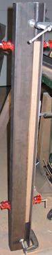
the color of your choice. Take the 2.5”x2.5”x1/8” 4-foot angle-iron and the 4-foot
rectangular tubing and mate them together so that the inside of one leg of the
angle-iron is touching one of the 3” faces of the 2” x 3” tubing. We need a
little bit of space between the other leg of the angle-iron and the tubing, and
we want that space to be pretty constant (or the tubing won’t be parallel to
the front of the saw). To do this, I ripped a piece of oak to the width I
wanted and sandwiched it in there as a spacer (make sure that you keep the
spacer away from the rounded inside corner of the angle iron). Clamp everything
together securely. Then, bolt the pieces together. Note that we’re not completely
done with this part, yet. We still have to drill the holes for mounting it to
the front of your saw, but we’ll save that until after our fence is built so
that we can test-fit everything and make sure that we don’t mount the rail too
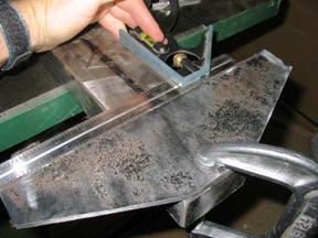
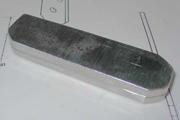
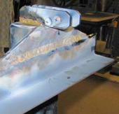
high or low. Now, we build the fence itself. For starters, we have to plug one end of the 3-foot tubing.
The challenge here is that this plug is going to be bearing most of the
clamping stress, so the weld needs to be fairly sturdy, but we’re also planning
on rounding the corners off, and we don’t want to accidentally grind all of the
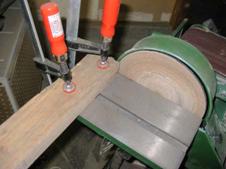
weld away. It’s fairly important that this plugged end be square to the
sides of the fence (or your whole clamping mechanism will be crooked). You can
see the photo of how I squared mine on the disc sander. I squared the table to
the disc, and then clamped a piece of 2x4 to the table that was also square to
the disc. Then, I was able to use the table and the 2x4 as a guide while
pressing the plugged end of the tube against the disc. Before you start, use a sharpie or some other felt marker to
scribble all over the end. This way, you’ll know when all of the end plug has
contacted the sanding disc. Next, weld or braze the spacer onto one of the 3-inch sides
of the fence tube. Remember that the spacer
needs to be flush with the end plug in the tube (where the clamp mounts are
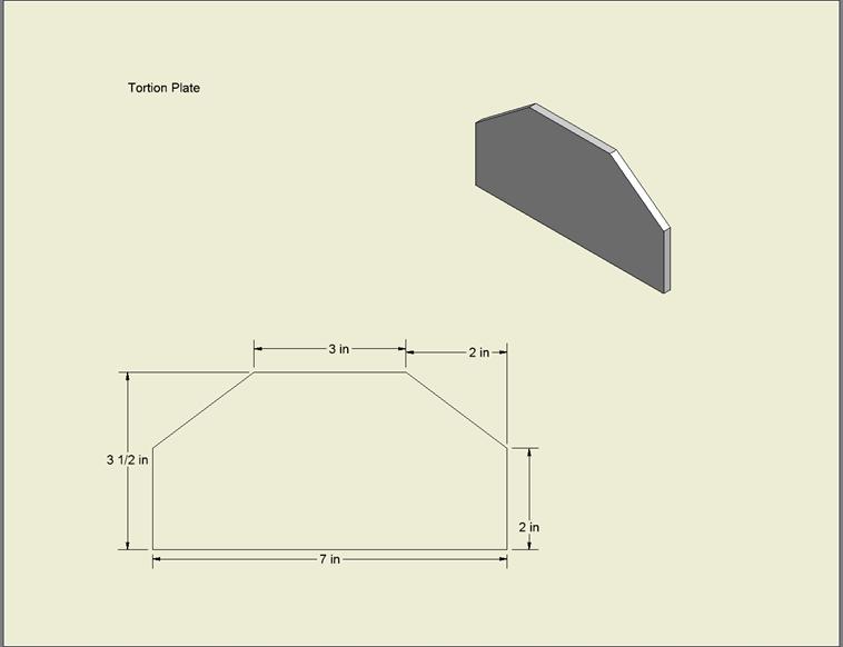
going to go). After that, weld or braze the tortion plate onto the spacer.
Again, make the the narrow part of the tortion plate (the “top” of the trapezoid,
if you will) flush with spacer and the end plug in the tube. Try to get the
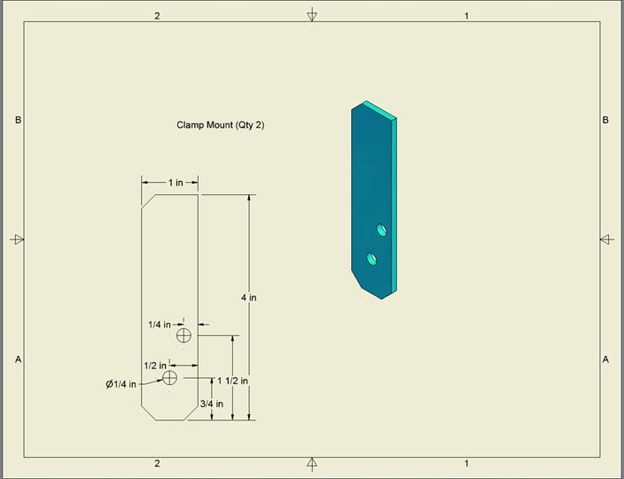
wide-end of the tortion plate perpendicular to the tubing. Now for the clamp mounts. Drill the holes in the clamp mounts.
We want these holes to be lined up with one another, so I stuck mine together
with carpet tape so that I could drill through them both at the same time. Also,
the mounts are beveled for appearance and to have smooth corners. You don’t
have to make them 45-degrees. You can make them semi-circles, or you can just
file the sharp edges down, whatever your preference. (While your welding/brazing stuff is cooling, this is a good
time to go see if the epoxy on your knob-block has cured. If so, go toss it in
the drill-press and sand it until you have a round knob. Then, paint it and let
it dry.) Next, prepare your adjustment bars. You need to have some little
UHMW pads on them for good sliding, so I used my band-saw to make some thin
strips suitable for epoxying onto the ends of the bars. If I were to do everything
over again, I’d just use the sticky-backed ¾” UHMW tape you can get from Woodcraft
or One bar goes on each “leg” of the squaring angle-iron. The
one that goes underneath the top leg just levels the fence and makes it ride a
little off of the saw table, and can be positioned anywhere, so I clamped it
about ¼” in from the edge of the angle. The other bar is the one that you use
to adjust for squareness and it bears a lot more force than the top one does,
so I wanted mine to be as close to the corner of the guide tube as possible to
minimize flexing and deformation of the tubing when I clamped. So, I placed
that bar about ¼” down from the corner of the guide tube. But, in order to do that, we’re going to need to know how
the fence is going to ride on the tubing. To do this, I placed the fence on the
saw table and then set up two outfeed rollers to hold my guide tube. Then, I
could raise or lower the guide rail/tube to help visualize everything. Be sure
to slip your top adjustment bar in between the guide-tube and the squaring
angle. Once you do this, you’ll have an idea of where on the angle-iron to
place the second adjustment plate. Once you’ve got the placement all figured out, go ahead and
clamp them. Figure out where the center of the UHMW pads are and mark those
four positions on the angle-iron. This is where our adjustment screws are going
to go. Now, if you’re going to rivet the bars in place, go ahead and drill the
holes. I used 3/16” rivets, but 1/8” would do fine, too… I just didn’t have any
1/8” ones handy that were long enough. Make
sure to put the rivets within ¾” of the side of the fence tube. That way,
they’ll be obscured by the ¾” melamine sacrificial fences that we’re going to
attach. Otherwise, if they’re further out than that, there’s a chance that
they’ll stick up past the surface of the table, and they’ll scratch or gouge
your work when you use the saw. However, if they’re hidden under the
sacrificial fence, then you’re safe. So, I’d put them about ½” out from the
sides of the fence. Once you drill the rivet holes, don’t put the rivets in
quite yet… and, if you’re spot-welding, don’t weld quite yet, either. We want
to drill and tap the holes for the adjustment screws and we want the adjustment
bars out of the way for that. These holes should be in line with the centers of
the UHMW pads on the adjustment bars (and you already marked those spots on the
angle-iron, remember?). For the adjustment holes, I used 10-24 sized headless allen
screws. Once you drill and tap your adjustment screw holes, you can go ahead
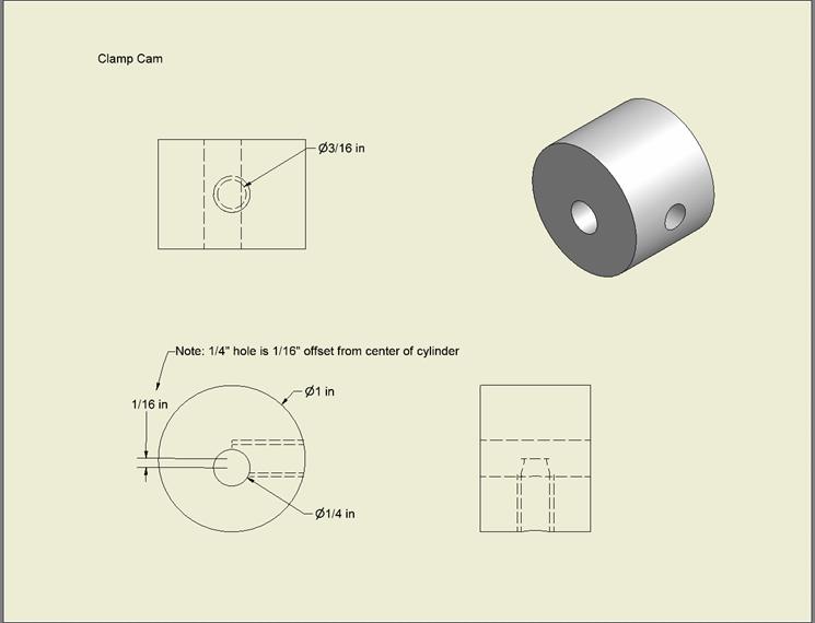
and weld, rivet, or epoxy your adjustment bars in place. Next, we’re going to make the clamping cam. Grab the ¾”
long, 1” diameter rod cylinder thingie. Find the center of one of the circular
faces by measuring ½” in from various places along the circumference. Once
you’ve found the center, mark a spot about 1/16” out from the center (It
doesn’t matter which way you go… it’s a circle). Drill a ¼” hole down through
the cylinder at this off-center point. You now have a cam. Now, we just need to know where to put
the hole for the lever. Go ahead and place the cam between the clamp mounts and
put one of the long ¼”-20 bolts through it to mount it in place. Now, you
should be able to spin the cam around and around and see the cam action at
work. Turn the cam until it gets closest to the opposing leg of the angle-iron
(when there’d be the most clamping on the guide tube). At this point, we’d want
the clamping lever to be all the way down, so make a little mark with a sharpie
or something on the bottom of the cam. Now, turn the cam 180-degrees as though
you were lifting the clamping lever. You should see that, with the lever
vertical, the cam would be as “unclamped” as possible. Once you’re satisfied with the positioning of where your
lever is going to go, go ahead and drill a hole where you placed your mark (for
drilling into a curved surface, it helps to use a center-punch to make a little
dent to help your drill not stray when you first start the hole). Then, tap the
hole to 5/16”-18. Once you do that, if the paint on your clamping lever knob is
dry, you can put a 5/16”-18 jam nut on the threads of the lever and put the
lever on the cam. Screw the knob in until you hit the ¼” pivot bolt, then back
out about one turn and use the jam nut to wedge the lever in place. Next, fashion a little pressure plate out of the ¾” strip
steel/brass. I was able to make mine with a vise, repeatedly squishing the end
until I had a tight loop on one end. Drop that in place and put the other
1/4”-20 bolt through it. Drill and tap the hole for the slider for the back rail. At this point, the fence is done except for addition of
sacrificial fences and adjustment. We can now drill the holes to place the
front rail. Use the adjustment screws to push the adjustment bars out a bit
(since we’ll want some room to back them off if we need to). Now trial-fit the
guide-rail. Raise the rail/tube until they just
start to lift the fence off of the saw table. Make sure that the rail does not get in the way of your miter slots!!
For me, the top of the rail was ½” below the top of the table, and the miter
slots are about 7/16” deep, so I had about 1/16” of clearance. In your case, if everything lines up fine, then figure out
where you need to drill your holes and drill them. However, if your rail does get in the way of your miter slots,
then you have a few options. If the rail is just barely in the way, you can
mount the rail a little lower and just screw the adjustment screws further. Or,
if the rail is really in the way (for
example, more than about 1/16” of overlap, then you can either grind a groove
in your angle-iron for your miter slots (some commercial T-square fences come
like this) or you can go get an angle-iron with one leg a little shorter (like
a 2”x2.5”). Once you drill your holes and mount your front rail, you
should be able to place your fence on it and lock the fence to the guide tube.
Go ahead and lock the fence and see how sturdy the other end is. It should feel
pretty solid. Now mount your rear rail the same way you mounted the front
one. The only difference is that I mounted my rear rail “upside-down” in the
sense that the horizontal leg (that the fence was going to ride on) was over the vertical leg (that bolts to my
saw). I used 1.5”x1.5” 3/16”-thick angle-iron because a bigger piece would
interfere with my blade-guard (or the mount where it clamped on when I used to
use it, anyway). Once this is in place, put the ¼”-20 nut on the ¼”-20 1-inch
bolt and thread it into the hole at the far end of the fence. Cut a little
piece of UHMW tape to fit the end and then adjust the bolt so that the end
rides just off of the top of the
table and then lock the bolt with the jam nut. Do the same with the vertical adjustment screws… adjusting
so that the fence rides just off of the top of the table. Slide the fence from
side to side to be sure that it doesn’t “bottom out” anywhere. Lastly, we need to adjust for squareness and clamping
snugness. With your table-saw unplugged, raise the blade all the way
and slide the fence up against the blade and lock the fence. (Be careful because the fence is going to
twist a little when you clamp it). Unless you live a charmed life, the
fence will be touching only one end of the blade, the front end or the back
end. Measure the gap at the place were the blade is not touching with some feeler gauges or tiny drill bits or whatnot.
Basically, every quarter-turn of one
of the 10-24 adjustment screws will give you about a 1/100” correction in gap
across the diameter of a 10” saw blade. So, adjust until you are satisfied with
the degree of parallel. To get the clamping snugness right, you need to turn both of
the squareness adjustment screws the same amount. Adjust the screws so that the
fence is pretty well clamped when the lever is about 45-degrees down from
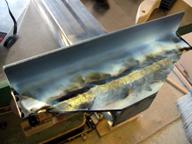
horizontal. All of the home-made fences I’ve seen had some kind of paint
on them. Usually, it’s grey. I opted for green Hammerite because it would match
my Grizzly saw. If you’ve never seen it before, Hammerite is this paint that
gives that orange-peel-like hammered finish. It comes in brush-on and spray.
The spray doesn’t give you as good of a hammered effect as the brush on, but
it’s a less muss and fuss, so I went with spray. Be sure to mask off the parts where the paint would get
boogered up. Specifically, these are: When you mask off the strips where the adjusting strips
contact, use something like 1-inch masking tape, since the strips, themselves,
are ¾”. This will give you 1/8” on either side for slop. Lastly, you can make the little window for viewing the
measuring tape. At my local Home Depot, about the thickest sheets of Lexan that
they sell are 0.1” thick. Since it was closer to ¾” or more between the top of
the tortion plate and the top of the guide tube, I decided to make a big “lexan
sandwich” using clear silicone rubber adhesive (I tried about 5 different clear
adhesives and that was the only one that didn’t cloud the lexan). However, it occurred
to me later that you could easily make a little wooden piece that mounts on the
tortion plate and closes most of the gap and then you could glue a little piece
of lexan on the bottom of the wood. Either way, don’t forget to make it
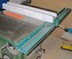
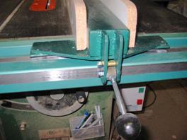
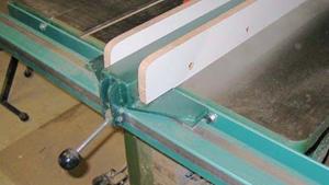
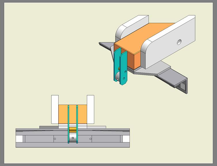
adjustable from side-to-side by about ¼”. When you’re all done with painting and you put it all back
together, you should end up with something like so:
![]()
Parts

Construction
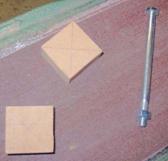
 Cut two 1.5”x1.5” pieces of ¾” MDF
and draw lines between the opposing corners on them to find the centers of the
pieces. In one piece, drill a 5/16” hole all the way through. In the other piece,
use a ½” or 5/8” forstner bit (or whatever you’ve got) to drill a shallow cup
a little deeper than you need to receive the hex head of the 5/16” bolt that
we’re going to use for the clamping lever.
Cut two 1.5”x1.5” pieces of ¾” MDF
and draw lines between the opposing corners on them to find the centers of the
pieces. In one piece, drill a 5/16” hole all the way through. In the other piece,
use a ½” or 5/8” forstner bit (or whatever you’ve got) to drill a shallow cup
a little deeper than you need to receive the hex head of the 5/16” bolt that
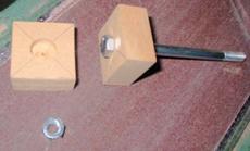
we’re going to use for the clamping lever.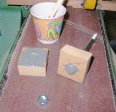 Mix some JB-Weld, PC-7, or some
other strong epoxy and goop some into the cup where the head of the bolt is
going to go. Then, thread the bolt through the 5/16” hole on the other piece,
slather a little epoxy on the faces, and clamp them together and let them sit
for a day.
Mix some JB-Weld, PC-7, or some
other strong epoxy and goop some into the cup where the head of the bolt is
going to go. Then, thread the bolt through the 5/16” hole on the other piece,
slather a little epoxy on the faces, and clamp them together and let them sit
for a day.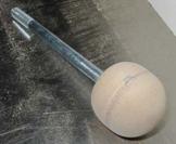 When the epoxy has cured (I’ll remind
you later to come back here for this part), remove the clamps and use a belt
or power sander to get round off the corners and edges.
When the epoxy has cured (I’ll remind
you later to come back here for this part), remove the clamps and use a belt
or power sander to get round off the corners and edges.
 Next, we’ll assemble the front guide
assembly, which is merely two pieces bolted together.
Next, we’ll assemble the front guide
assembly, which is merely two pieces bolted together.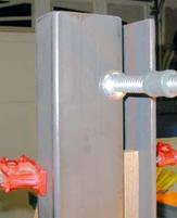 Then, drill a pair of 3/16” holes
through the angle-iron and the tubing where they overlap. Place them fairly
near the ends (about 6” or so in from the ends is fine) to best resist any torque
exerted by the fence upon the guide tube. Line the holes up with a line that
runs down the middle of the area where the two pieces overlap each other (not
too close to the edge of the angle-iron, nor the tubing).
Then, drill a pair of 3/16” holes
through the angle-iron and the tubing where they overlap. Place them fairly
near the ends (about 6” or so in from the ends is fine) to best resist any torque
exerted by the fence upon the guide tube. Line the holes up with a line that
runs down the middle of the area where the two pieces overlap each other (not
too close to the edge of the angle-iron, nor the tubing).
 Once you’ve drilled the holes, unclamp the pieces and
re-drill the holes in the angle-iron
to be ¼” at a minimum (to accommodate
the ¼” bolts that we’re going to use). If you need more room to adjust for parallel
or whatnot, feel free to make these holes a little bigger… 5/16”, I guess. Then,
tap the holes in the tubing to ¼”-20.
Once you’ve drilled the holes, unclamp the pieces and
re-drill the holes in the angle-iron
to be ¼” at a minimum (to accommodate
the ¼” bolts that we’re going to use). If you need more room to adjust for parallel
or whatnot, feel free to make these holes a little bigger… 5/16”, I guess. Then,
tap the holes in the tubing to ¼”-20.
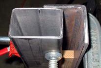
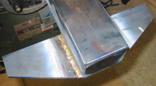
 What I ended up doing was beveling the edges of the 3”x2”x1/4” plate by about
5-10 degrees, to make fit the end of the tubing like a square cork, of sorts.
I tapped it snug (don’t tap it too hard or you’ll deform the tubing) and then
welded the two pieces, filling the little groove around the end with weld metal.
I then rounded the corners off on the belt-sander. (Note, the little gap at
the front of your belt-sander, between the roller and the table, is great for
rounding things. Since the sanding belt has no backing there, you can place
things there and the sanding belt will “give” a little, wrapping around the
thing you’re trying to round off).
What I ended up doing was beveling the edges of the 3”x2”x1/4” plate by about
5-10 degrees, to make fit the end of the tubing like a square cork, of sorts.
I tapped it snug (don’t tap it too hard or you’ll deform the tubing) and then
welded the two pieces, filling the little groove around the end with weld metal.
I then rounded the corners off on the belt-sander. (Note, the little gap at
the front of your belt-sander, between the roller and the table, is great for
rounding things. Since the sanding belt has no backing there, you can place
things there and the sanding belt will “give” a little, wrapping around the
thing you’re trying to round off).![]()
![]()
 Then, weld or braze the squaring
angle iron to the tortion plate, lined up with the wide end of the plate. Try
to get this angle-iron to be square to the fence tube. If that means that it
can’t be perfectly flush with the wide end of the tortion plate, then that’s
okay.
Then, weld or braze the squaring
angle iron to the tortion plate, lined up with the wide end of the plate. Try
to get this angle-iron to be square to the fence tube. If that means that it
can’t be perfectly flush with the wide end of the tortion plate, then that’s
okay.
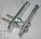
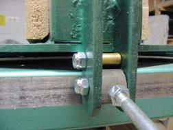
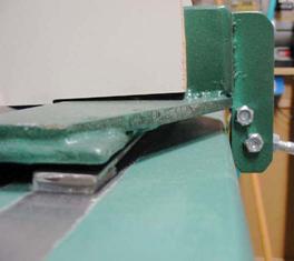
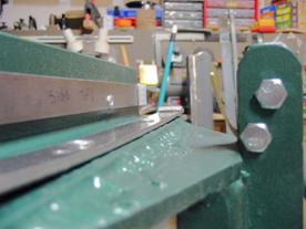
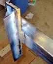
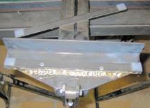
 Now, weld or braze the clamp mounts
to the end-plug/spacer/tortion-plate stack. You want these to be ¾” apart and
parallel. To keep them this way while I was brazing, I ran two bolts through
the holes with three nuts on each bolt to hold them parallel. The outside of
each mount should be 7/8” in from the side face of the fence tubing and the
top of the mount should be flush with the top of the fence.
Now, weld or braze the clamp mounts
to the end-plug/spacer/tortion-plate stack. You want these to be ¾” apart and
parallel. To keep them this way while I was brazing, I ran two bolts through
the holes with three nuts on each bolt to hold them parallel. The outside of
each mount should be 7/8” in from the side face of the fence tubing and the
top of the mount should be flush with the top of the fence.![]()
 Before we drill the holes for our
pop rivets (or spot-weld them, if that’s what you’re going to do), you’ll need
to clamp the bars where you want them to go. Don’t clamp them quite yet, I just
want to discuss placement of them, first.
Before we drill the holes for our
pop rivets (or spot-weld them, if that’s what you’re going to do), you’ll need
to clamp the bars where you want them to go. Don’t clamp them quite yet, I just
want to discuss placement of them, first. 
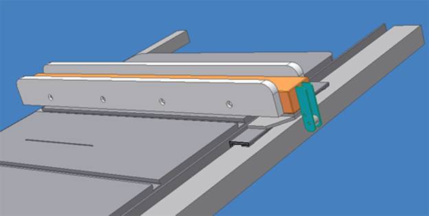
Finishing
Victory Lap (the finished photos)